
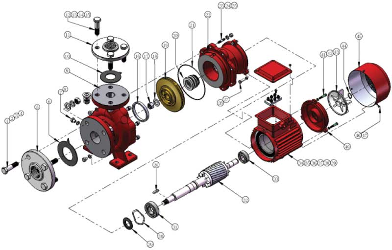
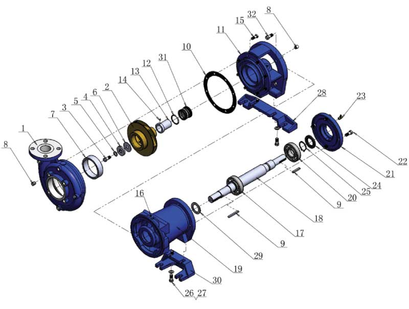
Design Advantages
-
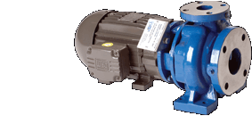
Heavy Construction
-
Large Operating Range
- Fewer models required
- Less inventory for wide product offering
-
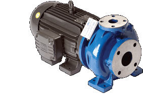
Flanged Connections
- Easy pump removal without disrupting piping
- Fewer leaks in the field at pump connections
-
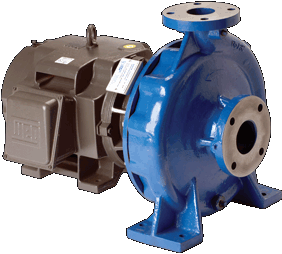
Cast with Feet Directly Under the Volute
- Ensures proper alignment can be maintained
- Provides pump support for installed piping
- Helps bearings and seals last longer
-
Gauge Connections on Suction and Discharge Ports
- Simplifies pressure gauge installation
- Enables troubleshooting of installed pumps
-
Back Pull Out Design
- Easy disassembly and servicing of pump
- Piping connections remain undisturbed
-
Center Line Suction and Discharge
-
Impellers Dynamically Balanced to ISO G6.3 Spec
 Click to Enlarge
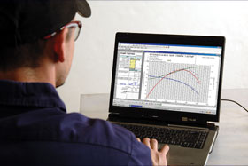
Selection Software
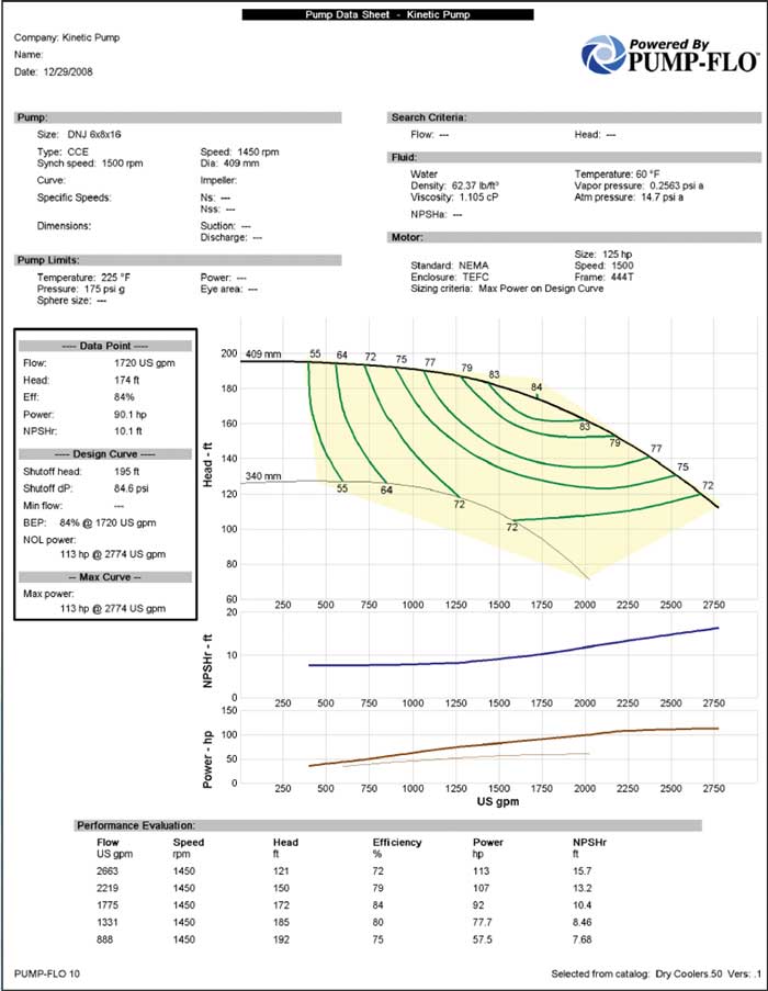
Kinetic pump model curves are generated by accurate test procedures and submitted to PUMP-FLO for analysis. Pumps can be selected and sized with full performance data via the Kinetic Pump website or by registering for a software CD for installation on your computer. The software provides curves for flow, pressure, brake horsepower, net positive suction head required (NPSHR), and efficiency. Pump speeds can be varied.
 Click to Enlarge
Engineering Drawings
2D and 3D drawings are available for all Kinetic Pump models for OEM’s and designers to incorporate into engineering projects. 2D drawings are available in DWG and DXF format. 3D models are available in SolidWorks and IGES format. Visit the downloads section to download the drawings.
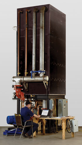
Pump Testing
- 2750 Gallon Test Stand
- 1 1/2", 2", 4", and 6" Centrifugal Pump Test Loops
- PC Based Data Aquisition and Control Platform
- Computerized Data Collection and Analysis for Pressure, Flow Capacity and HP
- Complete Test Run Data is Logged and Stored in Memory for Subsequent Print Out and Graphing
- Certified Test Reports of the Actual Pump Performance Curve
- Customer May Witness the Testing Upon Request
